Biography
Interests
Fawzi Mazek1*, Michael Johnson2 & Michael Goytan2
1Spine Fellow at Winnipeg Spine program, University of Manitoba, Manitoba, Canada
2Assistant Prof. Section of Orthopedics and Neurosurgery, Winnipeg spine program, University of Manitoba, Manitoba, Canada
*Correspondence to: Dr. Fawzi Mazek, Spine Fellow at Winnipeg Spine program, University of Manitoba, Manitoba, Canada.
Copyright © 2018 Dr. Fawzi Mazek, et al. This is an open access article distributed under the Creative Commons Attribution License, which permits unrestricted use, distribution, and reproduction in any medium, provided the original work is properly cited.
Abstract
Retrospective cohort study
To asses the neurological and radiological outcome of the posterior fixation and fusion of the cervicothoracic using screws and rod system.
Stabilization of cervicothoracic junction presents unique challenge to the spinal surgeon. Anatomic characteristics of the spinal cord, vertebral segments, and the biomechanical properties of the spine markedly alter over a relatively short anatomic distance and create a unique transitional region.
Between May 2000 and August 2007, a total of 590 screws were implanted in 37 consecutive patients undergoing posterior screw rod fixation and fusion of the cervicothoracic spine. All instrumentation crossed the cervicothoracic junction with lateral mass screws were placed in the cervical spine and pedicle screws in the thoracic spine.
Bony fusion was recorded in all cases on CT evaluation. There were no infections, and there were no failures of posterior fixation. However, there was one mechanical failure of anterior fixation at C7-T1. Complete or partial neurological recovery was observed in 19 of 22 patients. The initial neurological status of these patients was Frankle B, C or D. Eight of the 14 patients with Frankel A shows one level root improvement and 6 patients failed to show any neurological improvement.
The high rate of fusion observed in these patients justified posterior fixation with screw and rod system. Considering the few mechanical failure observed the choice of the posterior approach with using screws and rod system was appropriate for fixation at the cervicothoracic junction for different pathology. Insertion of pedicle screw in the upper thoracic portion T1-T3 requires a careful technique and knowledge of the posterior projection points of the pedicle and their orientation in spaces. However, it is a very reproducible and safe technique with excellent results.
Introduction
Stabilization of cervicothoracic junction presents unique challenge to the spinal surgeon [1-7]. Anatomic characteristics of the spinal cord, vertebral segments, and the biomechanical properties of the spine markedly alter over a relatively short anatomic distance and create a unique transitional region [2]. The cervicothoracic junction as a surgically relevant unit can be considered from C5-T5. Six specific challenges must be addressed and overcome for successful stabilization of the cervicothoracic junction.
1.Variation in size and morphology between the cervical and thoracic spinal segments;
2. Transition of the cervical lordosis curve to the thoracic kyphotic curve;
3. Variation in the degree of the mobility between the flexible cervical spine and the less mobile thoracic spine;
4. Surrounding anterior thoracic visceral structures;
5. Need for specialized spinal implants required to transition between the variances in morphology of spinal segments “lateral mass screw in the cervical spine and pedicle screw in the thoracic spine;
6. Limitation of exposure via posterolateral approach due to vertebral artery [3]. Therefore lesions in the cervicothoracic junction present a significant clinical problem for diagnosis, treatment and prognosis.
Previous study showed that there were no statistically significant difference between the combined anterior plate/posterior instrumentation model and posterior instrumentation-only model [8,9].
Historical perspective using different approaches has been described in the literature including cervical facet wiring interspinous wiring, sublaminar wire, laminar clamps, and lateral mass plates with screws. Wiring methods and clamps effectively reconstitute the posterior tension band and can be used alone or to supplement other constructs, but its mechanical stabilizing potential is limited, it does not result in rotational or translational sagital stability and additional external fixation is needed which is great disadvantage, particularly in rheumatoid arthritis and metastatic disease. Sublaminar wires and laminar hooks also carry the risk of neurovascular injury [10].
Lateral mass plate systems are biomechanically superior to laminar wire or clamp fixation in limiting cervical motion. In addition unlike posterior laminar wiring or clamping, lateral mass plating does not require the presence of the posterior elements, which are often removed to facilitate decompression. Lateral mass plate, however, are not optimal for use in patient with cervical degenerative spondylosis related abnormal curvatures because the plates are difficult to contour and the screw positions are dictated by the plate’s entry holes. In addition most of the system does not easily allow extension of the fusion to the thoracic spine. It is suboptimal for cervicothoracic fusion because it require connector device at the cervicothoracic junction, which decrease the rigidity of the system [8]. Advancement in posterior cervical fixation has moved from a wiring procedure to hook and plate-screw system and more recently toward the versatile rod-screw systems [10]. Clinical and radiological outcome of the posterior fixation of the cervicothoracic junction only using rod-screw system is not well documented.
In this study, we review our clinical experience with the polyaxial screw-rod system, including the clinical and radiological outcomes of our 37 patients. In addition, we suggest detailed surgical techniques to reduce associated complications.
Methods
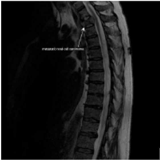
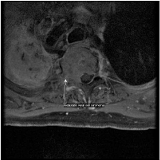
Between May 2000 and August 2007, A total of 590 screws were implanted in 37 patients underwent posterior instrumentation and fusion of the cervicothoracic junction for different diagnosis. 22 patients who sustained unstable fracture between C5-T1, 3 patients who had pathological fracture secondary to metastasis, 6 patients had cervical spondylotic myeloradiculopathy, 6 patients had rheumatoid arthritis with cervical myelopathy, and one patient had psoriatic cervical myelopathy.
There were 21 patients male and 16 female aged between 16-92 with an average 54. Neurologically on initial presentation is 14 patients were classified as Frankle A, 6 Frankle B, 9 Frankle C & 8 Frankle D.
Posterior Stabilization was performed using rods and top loading polyaxial screws in all the 37 cases with an average number of the total level instrumented are 7 levels, average number of level instrumented in the cervical spine is 4 levels and an average number of levels instrumented in the thoracic spine are 3 levels. Cross-Links have been used in 13 cases.
All the cases were associated with spinal cord decompression and fusion, The 3 metastasis cases were associated with anterior procedure “vertebrectomy and reconstruction with PMMA” and 10 of the trauma cases were associated with anterior procedure “ACDF”.
18 patients had a single 3.5-rod with 3.5 screws both cervical and thoracic and 19 patients had a single 3.5- rod with 3.5 cervical and 4.5 thoracic screw.
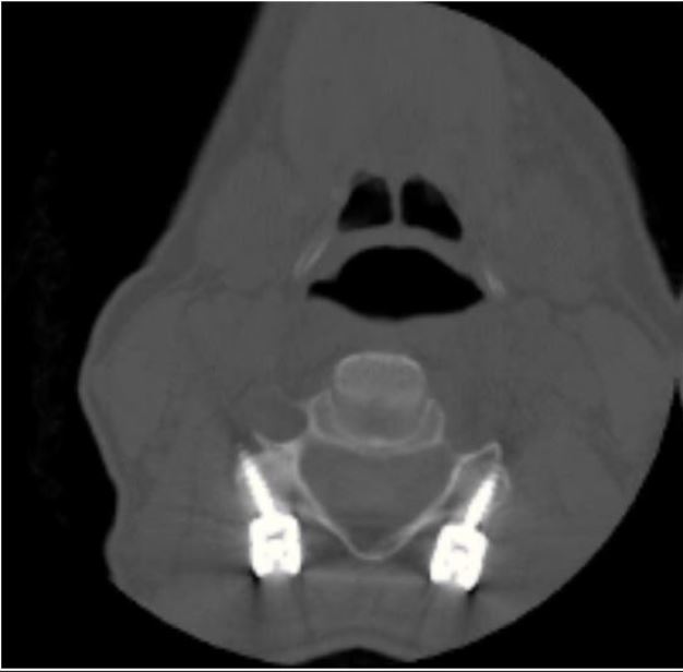
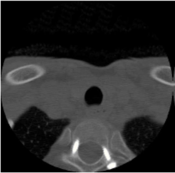
Follow up periods ranged from 6 to 30 months with an average 21 months. Two patient lost follow up after 6 months. 35 CT scans with sagittal and frontal slides were examined to evaluate the screws placement and fusion mass 6 months after the surgery.
Surgical Technique
The surgery was performed in a consistent fashion. Intubation was performed for cases with severe cervical stenosis or gross instability in an awake, fiberoptic fashion. The patient was then carefully turned to the prone position and the patient’s head was placed in a Mayfield clamp with fluoroscopic guidance to assess the spinal alignment as well as to localize the pathology. All cases done over Jackson table. The patient could then be prepped and draped in the standard fashion. A standard midline incision was made that exposed all the levels to be fused. The lateral masses were exposed in a subperiosteal fashion to the lateral margins of the facet joints. If needed, reduction of the locked facets was performed with the use of a high-speed burr and a double-ended micro-elevator. Once the deformity was reduced, the lateral masses to be fused were decorticated with the burr. Great care was taken not to disturb the capsule at adjacent levels in order to prevent any potential risk of iatrogenic instability and premature degeneration. Lateral mass screws were used from C3 to C7, and pedicle screws were used at thoracic spine. Screw insertion was always performed prior to laminectomy.
Details and recommendations regarding screw insertion at each level and the selection of screws are included in the discussion.
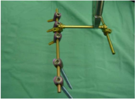
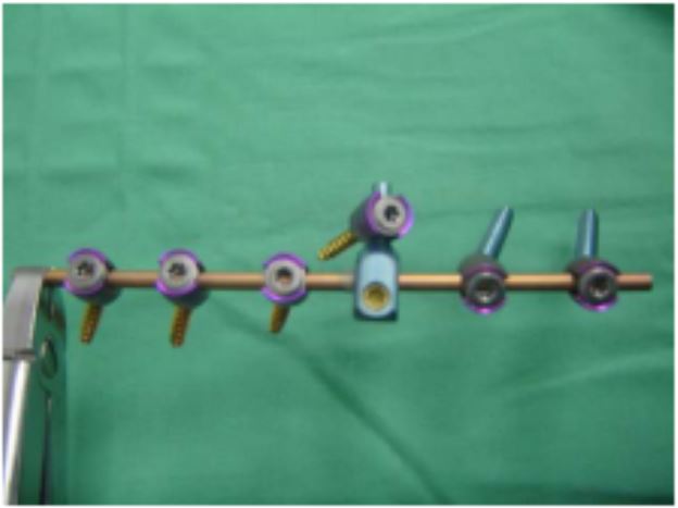
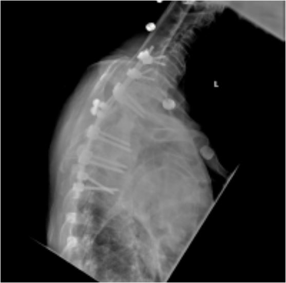
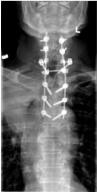
After screw placement, a decompressive laminectomy was performed. A rod was prepared to the appropriate length and contour of the patient so that it would easily pass through the heads of all polyaxial screws. Once the rod was positioned, it was secured to the heads of the screws using inner locking threaded cap. The unique anatomy at C7 - T1 creates a divergent orientation of the screw heads where the trajectory of a C7 lateral mass screw is lateral and the T1 pedicle screw is directed medially. To contend with this problem an offset connector (figure 4) was utilized on either the C7 or T1 screw.
Bony fusion was performed by packing local autograft bone from the posterior elements into the facet joints and around the decorticated lateral masses, lateral to the rod. The morselized iliac crest bone is typically used if a long segment fusion is required and if there is insufficient bone from the posterior elements.
During the entire procedure, the retractors were Intermittently released to avoid denervation of the erector Spinae muscles. Routine closure was carried out and drains were left in place as needed.
ResultsBony fusion was recorded in all cases on CT evaluation. Post operatively there were no infections, and there were no failures of posterior fixation. However, there was one mechanical failure of anterior fixation at C7- T1. This was a case of bilateral jumped facets treated with anterior fixation and C6-T2 posterior fixation.
The length of stay in the hospital was from 10-14 days with an average of 12 days. The operation time was from 3-11 hours with an average of 7 hours. The estimated blood loss was from 300-1500cc with an average of 900cc.
In the evaluation of the early postoperative CT scans that were routinely performed in all patients, there was no a suboptimal trajectory with no resulting vascular or neurologic sequels. Based on dynamic X-rays, no pseudoarthrosis was noted according to our criteria and no symptomatic adjacent segment angulations have been revealed to date. Intra operatively, there were two cases of screw-induced lateral mass fracture during surgery. We converted the screw trajectory to the modified Roy-Camille technique and used 4mm rescue screws in those cases. Other than the aforementioned, there were no screw pullouts or hardware- induced complications.
Complete or partial neurological recovery was observed in 19 of 37 patients. The initial neurological status of these patients was Frankle B, C or D. Eight of the 14 patients with frankle A shows one level root improvement and 6 patients failed to show any neurological improvement.
Discussion
The cervical lateral mass screw and plate system has several advantages compared to wire/cable constructs. These include ease of application, lack of dependence on intact posterior elements, and immediate rigid fixation. Roy-Camille designed the first lateral mass screw plate system and published his extensive experience using these systems [11,12]. Newer screw-rod systems can now extend rigid internal fixation from the occiput to the high thoracic spine as well as to the sub-axial cervical spine, with variable screw placement to accommodate the complex anatomy. Several modifications on the Roy-Camille technique for lateral mass screw fixation have been proposed over the years [12-14]. Roy-Camille et al. [12] advocated using the mid-point of the articular mass as the starting point for screw placement in the subaxial cervical spine, and suggested that the surgeon drill perpendicular to the posterior plane of the spine and 10 laterally. The mid-point was determined by outlining the superior border at the cranial joint line, the inferior border at the caudal joint line, the lateral border of the lateral mass and the junction of the lamina and lateral mass forming the medial border.
Magerl’s group recommended starting the drill hole 2 - 3mm medial and superior to the apex of the lateral mass and angling 30 upward and 25 outward. In a cadaveric study, An et al. [14] sought to find the safest screw trajectory to prevent injury to the nerve root and vertebral artery. They found that the nerve root was at risk if the screws were placed with a marked cephalad direction. They recommended that the screws be inserted 30 laterally and 15 in the cephalad direction, starting 1mm medial to the centre of the lateral mass from C3 to C6 in order to avoid injury to the nerve root and the vertebral artery. The currently accepted modification of this technique places the starting point 1mm medial to the mid- point and angles the drill 15 - 20 rostrally and 20-30 laterally.The burr is used to mark the starting point and the drilling is started using a 2.3mm drill bit with a drill guide. The drilling commences in a vertical direction until the outer cortex is perforated.
The drill is then introduced in the aforementioned direction. To reduce the possibility of slippage of the marking burr and guide drill, a small diameter diamond burr is helpful for perforation of the lateral mass cortex and for the initial guiding of the drill. The depth to be drilled and the appropriate length of screw were determined based on the measurements obtained on the patient’s preoperative CT scans. The drill hole is tapped with a 3.5mm tap. To reduce the possibility of lateral mass fracture during subsequent screw fixation, drilling and tapping should be performed along the entire measuring length of each screw. Additionally, in order to insert the screw up to the measured length, a groove was set for each screw head at the medioinferior side of the screw insertion point needing to be drilled. Although the screw system is polyaxial, slight inclination of the medial part of the lateral mass prevents the screw from advancing up to its entire length. From C3 to C7, most of the screws placed in our series had a lateral mass screw length of 16mm.
In accordance with this finding, Seybold et al. [15] reported in a 1999 cadaveric study of unicortical and bilateral mass screw placement that there were no statistically significant differences in pull-out strength between unicortical and bicortical screws. Thus, we do not routinely attempt to use bicortical screws during lateral mass screw fixation in the subaxial cervical spine.
Although a lateral mass screw can be placed at C7 as described above, the lateral mass at C7 is somewhat elongated in a rostro-caudal direction, and is thinner [16] so a pedicle screw may be more appropriate at C7. If a lateral mass screw is to be used at C7, great care must be taken so as not to insert too long a screw and injure the C8 nerve Root. The use of short screws (12mm) and the use of more cephalad and lateral directions of screw trajectory can reduce the chance of nerve root injuries [17].
A thorough knowledge of thoracic vertebral and perivertebral anatomy including spinal cord, aorta and rib articulation is essential to understand and perform “Free-hand” pedicle screw placement technique. There are several consistent dimensions to the thoracic vertebrae for which there is general agreement in the literature despite the high interindividual variability [18,19].
The transverse pedicle diameter is the critical anatomical variable on safe placement of the pedicle screw. Usually the lower thoracic spine (T10, T11 and T12) has the biggest pedicles varying from 6.3mm to 7.8mm. The transverse pedicle diameter of the mid-thoracic pedicle from T4 to T9 has the smaller pedicles varying from 4.7 to 6.1mm. Usually the pedicle between T4 [18] and T6 [20] has the smallest pedicles while the largest is at T12. The T4 through T1 pedicles tend to become progressively larger (diameter between 5.6mm and 7.9mm) when moving in a cephalad direction when analyzed in CT [21] and cadaver [18,20].
Misenheimer et al. [21] documented that the screw exceeds once the endosteal diameter of the pedicle, the pedicle will adapt in one of three ways: pedicle expansion, pedicle cutout by screw threads, or pedicle fracture. Pedicle changes occurred when greater than 80% of the outer cortical diameter was exceeded. In 72% of cases the fracture occurred laterally, with 28% medial occurrence. At all levels, the medial cortex is 2-3 times thicker than the lateral cortex [20]. Recently Rinella et al. [22] demonstrated the viscoelastic expansion of the pediatric scoliotic pedicle of 9-year-old boy, allowing 196% expansion before failure based upon CT scan measurement at the transverse internal diameter of the pedicle isthmus of one level. This data was equivalent to the 111% expansion before failure based upon CT scan measurement at the transverse external transverse diameter of the pedicle isthmus. Adequate pedicle screw length according to chord length is very important to prevent vascular or visceral complications. Another important landmark for safe screw placement is the distance from the dorsal lamina to the isthmus of the pedicle. The shape of the pedicle is quite variable. An oval shape occurs most consistently in the upper thoracic spine and the cephalocaudad and mediolateral dimensions are almost the same. Throughout the remainder of the thoracic spine, the pedicles have been described to have a teardrop or kidney-bean shape [20]. The nerve roots increase in size from approximately 3mm at T1 to 4mm at T12. The spinal cord directly abuts the medial aspect of the pedicle in a cadaver study [23,24]. In a similar study, dural sac is within 0.0-0.7mm of the medial pedicle in the thoracic spine [25].
Our “Free Hand” technique is equivalent for lumbar and thoracic pedicle screws placement using anatomical landmark and a specially designed gearshift based on three important principles: 1. starting point; 2. trajectory; 3. “intraosseous feel” of the pathway down the pedicle into the body. After the initial exposure, each step is repeated sequentially at each level to be instrumented.
After a meticulous exposure of the posterior elements to be fused the inferior 3-5mm of the inferior facet is osteotomized and articular cartilage on the dorsal side of the superior facet is completely removed except for the lowest instrumented vertebra. The base of the superior articular process is very important landmark to the ventral pedicle. A 3.5mm acorn-tipped burr is utilized to create a posterior cortical breach, approximately 5mm in depth. The pedicle “blush” may be visualized suggesting entrance into the cancellous bone of the pedicle. This may not be seen in smaller, apical concave pedicles because of very limited intrapedicular cancellous bone. In this situation, the tip of a probe may be required to find this in a funnel-like technique. The ventral lamina (roof of the spinal canal) can be palpated by percussion and ventral lamina invagination can be avoided. The path down the pedicle is then continued medial into the body with an ultimate depth averaging 30-35mm for the proximal thoracic region in adolescents and most adults. Rotate the finder 180 degrees to make room for the screw after advancing the finder to the approximate length of the desired screw. Make sure you feel bone the entire length of the pedicle. The surgeon must pay strict attention to the axial and sagittal position of the vertebrae in space to position the probe down the pedicle shaft appropriately. In addition, probing of the pedicle with the thoracic gearshift should proceed in a smooth and consistent manner with a snug feel because of the small size of the thoracic pedicles. Any sudden advancement of the gearshift suggests penetration into soft tissue and thus a pedicle wall violation or vertebral body violation. These should be investigated immediately in order to possibly salvage the pedicle and avoid complications. With the sounder in the base of the anticipated pedicle tract after confirming five intraosseous borders, mark the length of the tract with a hemostat and measure it.
If the tract appears too shallow, consider replacing the gear shift and advancing to the appropriate length. Place the screw slowly down the pedicle into the body in the same alignment to confirm it is threaded properly and allow for viscoelastic expansion. It is advantageous to have a variety of pedicle diameters and lengths available. Next assessing the pedicles, the most common method is AP and lateral radiographs. These should be reviewed carefully in all cases.
The use of electrical stimulation of the thoracic pedicle screw is advocated by some authors we did not use this technique [26]. Postoperative CT scanning did not reveal untoward placement of screws nor were there any clinical neurologic sequels to suggest a malpositioned screw.
As was previously mentioned, bony fusion was performed with a morselized posterior element bone with or without the iliac bone into the facet joints and around the decorticated lateral masses, lateral to the rods. Bony fusion has been achieved in all our cases confirmed by CT scan done at 6 months follow up.
Conclusion
Posterior instrumentation utilizing a screw and rod system was optimal for fixation at the cervicothoracic junction for a variety of surgical pathologies. The spine surgeons is afforded an opportunity to extend the instrumentation cephaled or caudal as needed even extending to the occiput or lumbar spine.
Considering that there were no mechanical failures and a fusion of all cases, a posterior screw rod construct is a safe, reliable and, reproducible choice for posterior fixation of the cervicothaorcic junction.
Bibliography


Hi!
We're here to answer your questions!
Send us a message via Whatsapp, and we'll reply the moment we're available!